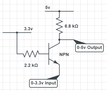
3v to 5v Level Shifter
The below circuit uses a BJT to shift a 0-3.3v data signal into a 0-5v signal. Specifically, 0-2.4v on the input will result in a logical 0 on the output, while 2.4v to 3.3v on the input will result in a logical high on the output. This happens because the NPN transistor is closed once the base voltage is greater than a diode drop (0.7v) above the input (ie the BJT closes once the input voltage reaches 3.3 - 0.7 = 2.4 volts)
Therefore the modes of operation are:
- Input is low, therefore the BJT is closed, driving the output low.
- Input is high, therefore the BJT is open, allowing the pullup resistor to pull the output to 5v.
Behaviour Analysis
To better understand the different operating modes of BJTs I took a closer look at exactly how the output voltage responds to a change in the input voltage. In the below oscilloscope image:
- the top plot is the input linearly increasing from 0v to 3.3v
- the middle plot is the resulting output
- the bottom plot is the calculated difference between the two
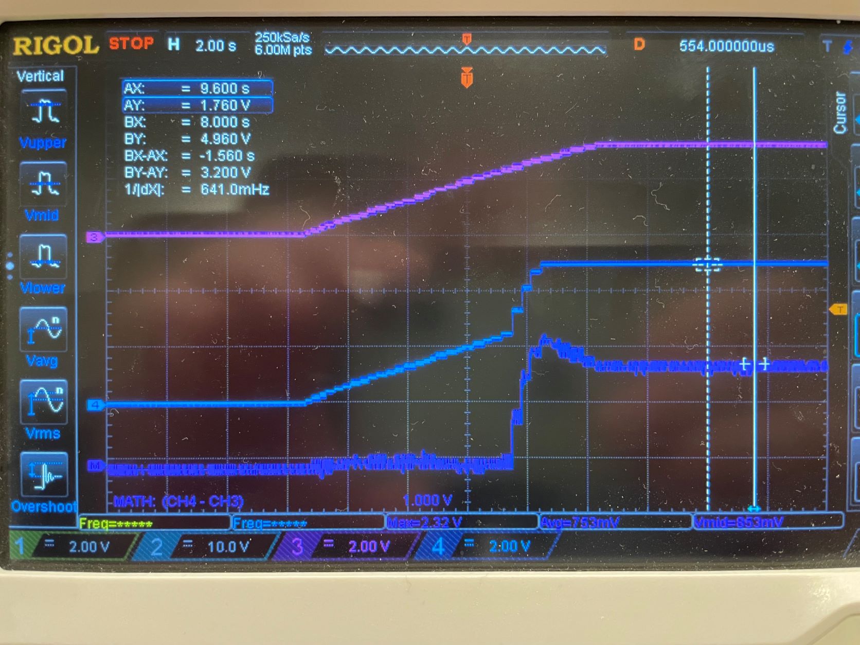
In this image we can see the BJT operating in three modes:
-
The first thing to notice is that the calculated difference between the two plots remains at
0in the input’s 0-2.3v range (the output linearly increases as the input increases). Put another way, the input and output are short circuited in this region, as expected for a BJT in saturation. -
From 2.3v to 2.6v volts on the input, the output rapidly increases up to 5v. This is the BJT in active mode, acting like an amplifier.
-
Finally, for any voltage on the input above 2.6, the output remains constant at 5v. This is the BJT in cutoff mode, the output is effectively disconnected.